Standing Lateral Spinopelvic Film
Three measurements are taken from the standing lateral view: pelvic incidence, sacral slope in standing, and proximal femoral angle in standing. This film captures the patient's functional upright pelvic posture.
Patient Positioning
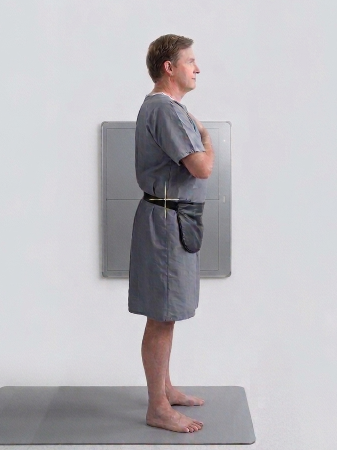
Patient stands upright, arms crossed over chest or resting on a support bar to avoid obscuring the pelvis. Feet shoulder-width apart, flat on floor. The cassette captures the full lateral spinopelvic silhouette from L1 to mid-femur. Ensure both femoral heads are superimposed.
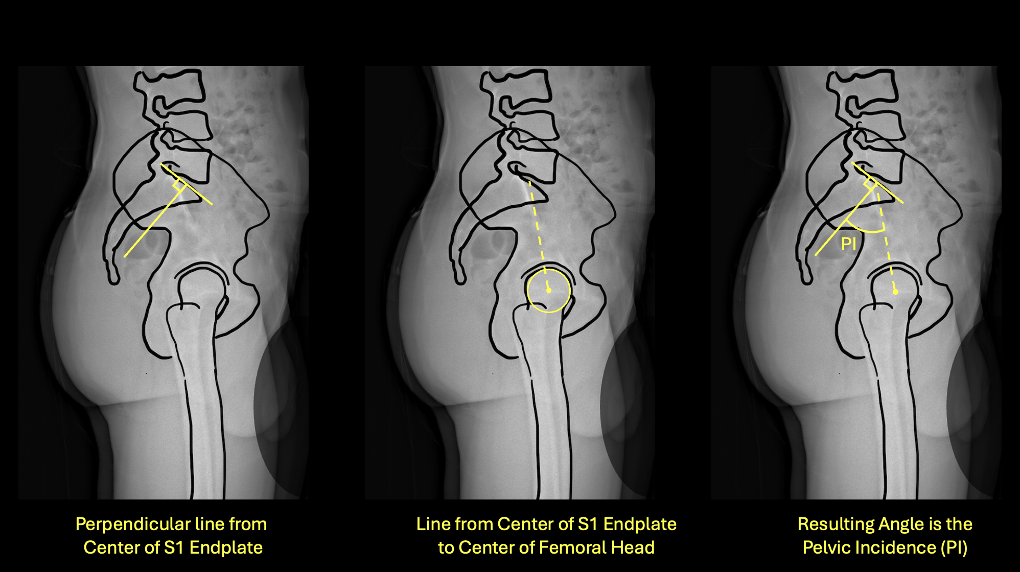
Left: perpendicular from S1 endplate center · Center: line to bicoxofemoral axis · Right: resulting PI angle
How to Measure
- 1Identify the center of the S1 superior endplate on the lateral film.
- 2Draw a line perpendicular to the S1 endplate at its midpoint.
- 3Draw a second line from that midpoint to the center of the bicoxofemoral axis (midpoint between both femoral head centers).
- 4The angle between these two lines is the Pelvic Incidence.
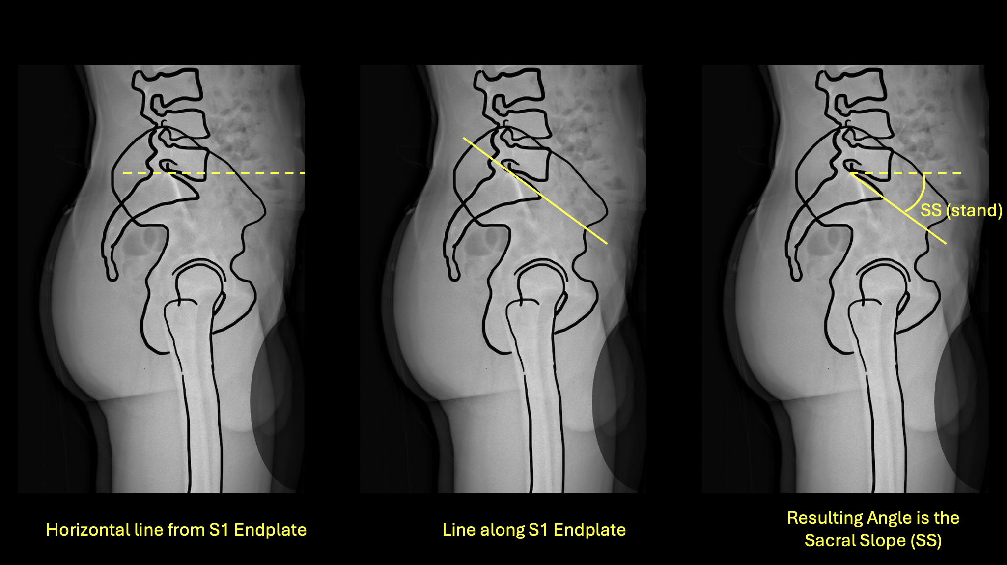
Left: horizontal reference · Center: line along S1 endplate · Right: resulting SS(stand) angle
How to Measure
- 1Identify the S1 superior endplate on the standing lateral film.
- 2Draw a true horizontal reference line.
- 3Draw a line along the superior surface of the S1 endplate.
- 4Measure the angle between these two lines — this is the sacral slope in standing.
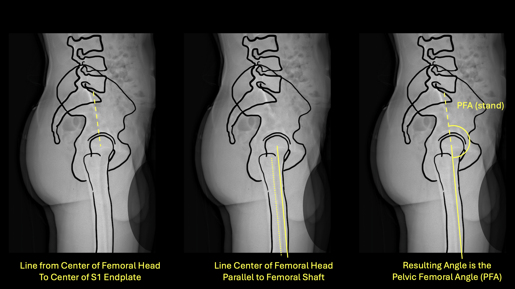
Left: line from femoral head to S1 · Center: line parallel to femoral shaft · Right: resulting PFA(stand)
How to Measure
- 1On the standing lateral film, identify the center of the femoral head and the center of the S1 endplate.
- 2Draw a line connecting these two points.
- 3Draw a second line parallel to the anterior cortex of the femoral shaft.
- 4Measure the angle between these two lines — this is PFA(stand).
Sitting Lateral Spinopelvic Film
Two measurements are taken from the sitting lateral view: sacral slope sitting and proximal femoral angle sitting. The delta between standing and sitting sacral slope (ΔSS) is the core input for mobility classification.
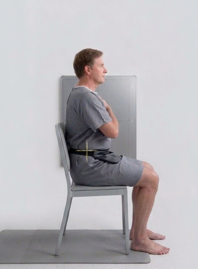
Patient Positioning
Patient sits on a firm, flat surface (not a soft chair). Thigh-trunk angle should be 100–110°, not 90° — this mimics the functional seated position in a chair. Back straight, arms crossed over chest, feet flat on the floor. Avoid lumbar flexion or slumping. This positioning standard is critical for reproducible ΔSS values.
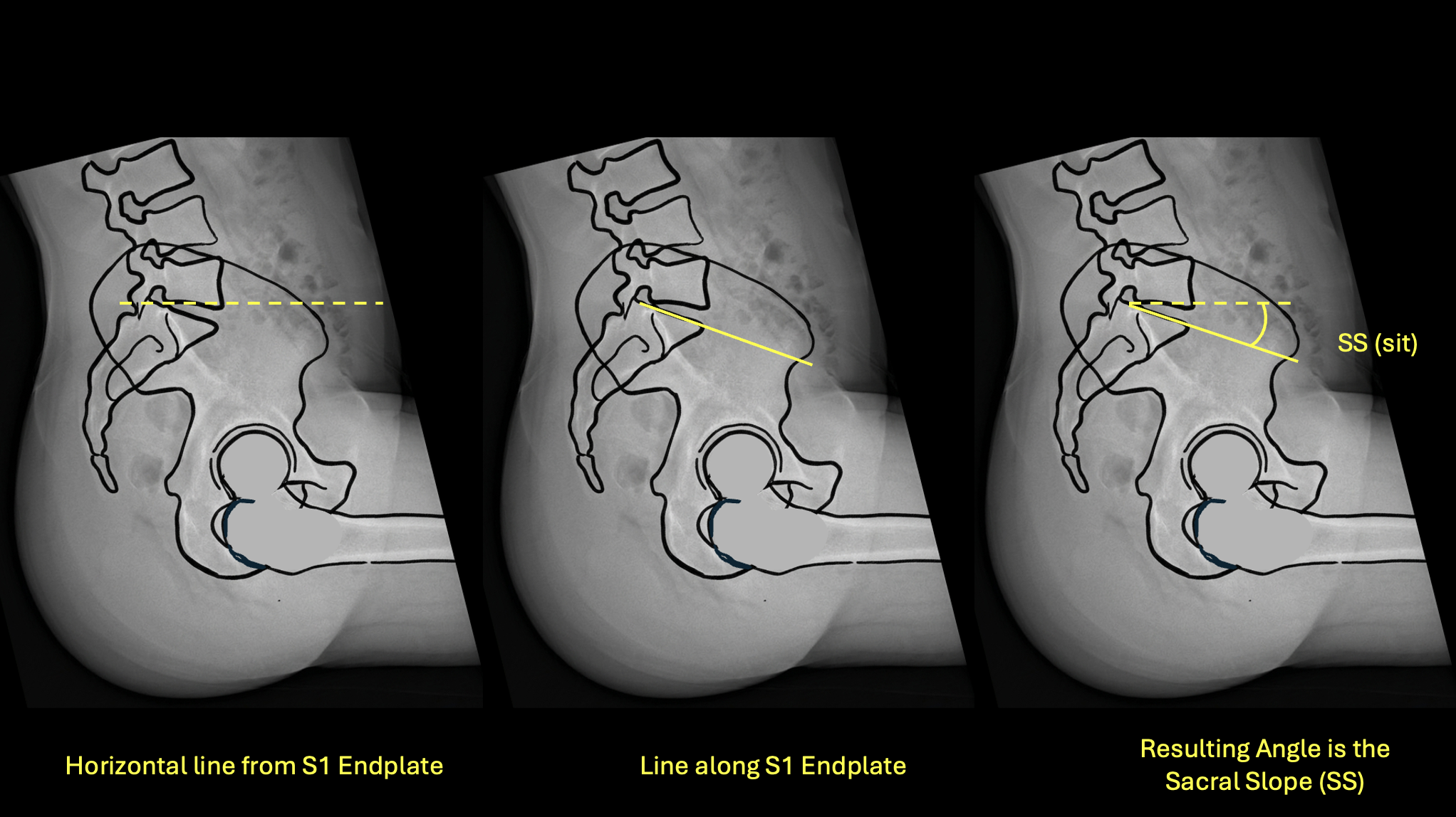
Left: horizontal reference · Center: line along S1 endplate · Right: resulting SS(sit) angle
How to Measure
- 1Identify the S1 superior endplate on the sitting lateral film.
- 2Draw a true horizontal reference line.
- 3Draw a line along the superior surface of the S1 endplate.
- 4Measure the angle — this is SS(sit).
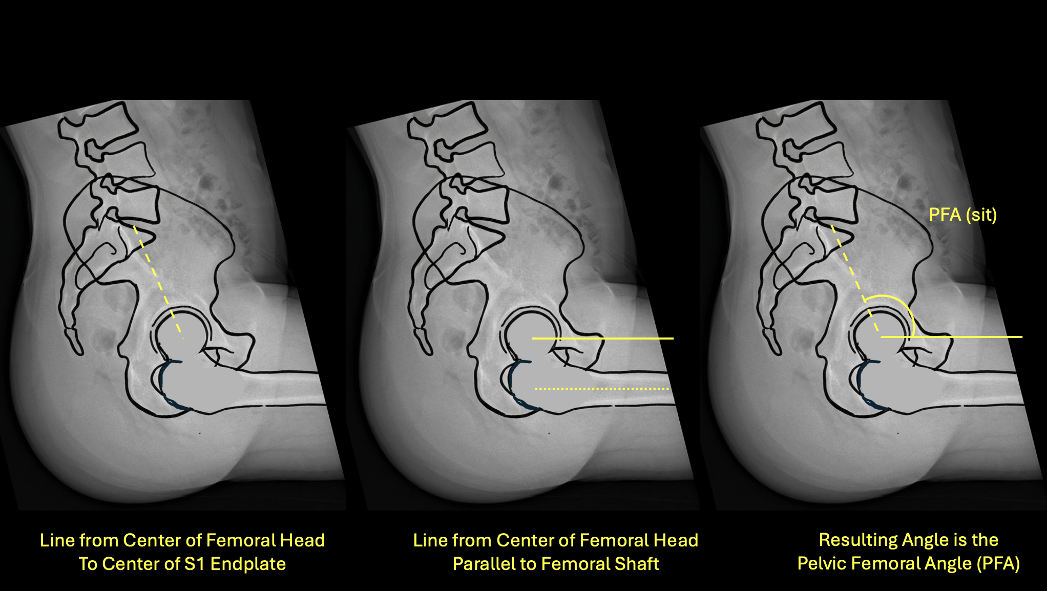
Left: line from femoral head to S1 · Center: line parallel to femoral shaft · Right: resulting PFA(sit)
How to Measure
- 1On the sitting lateral film, identify the center of the femoral head and center of the S1 endplate.
- 2Draw a line connecting these two points.
- 3Draw a line parallel to the anterior femoral cortex.
- 4Measure the angle — this is PFA(sit).
AP Pelvis Radiograph — Standing
The AP pelvis provides the anterior pelvic tilt measurement, which is used to correct functional cup anteversion targets for each patient's individual pelvic orientation.
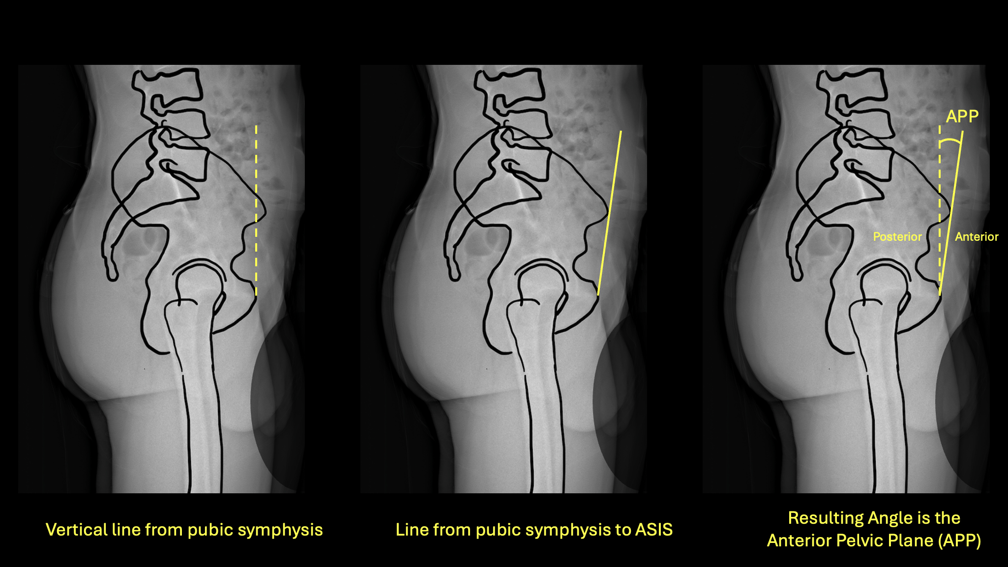
Left: vertical from pubic symphysis · Center: line from pubic symphysis to ASIS · Right: resulting APP/APT angle
How to Measure
- 1Identify the pubic symphysis and both anterior superior iliac spines (ASIS) on the standing AP pelvis film.
- 2Mark the midpoint between both ASIS.
- 3Draw a line from the pubic symphysis to this ASIS midpoint — this is the anterior pelvic plane (APP).
- 4Measure the angle between the APP and a true vertical line.
- 5If the ASIS are anterior to the pubic symphysis, the tilt direction is anterior. If the ASIS are posterior to the pubic symphysis, the tilt direction is posterior.